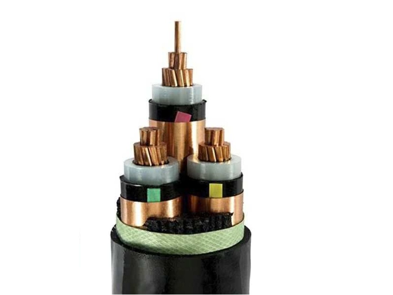
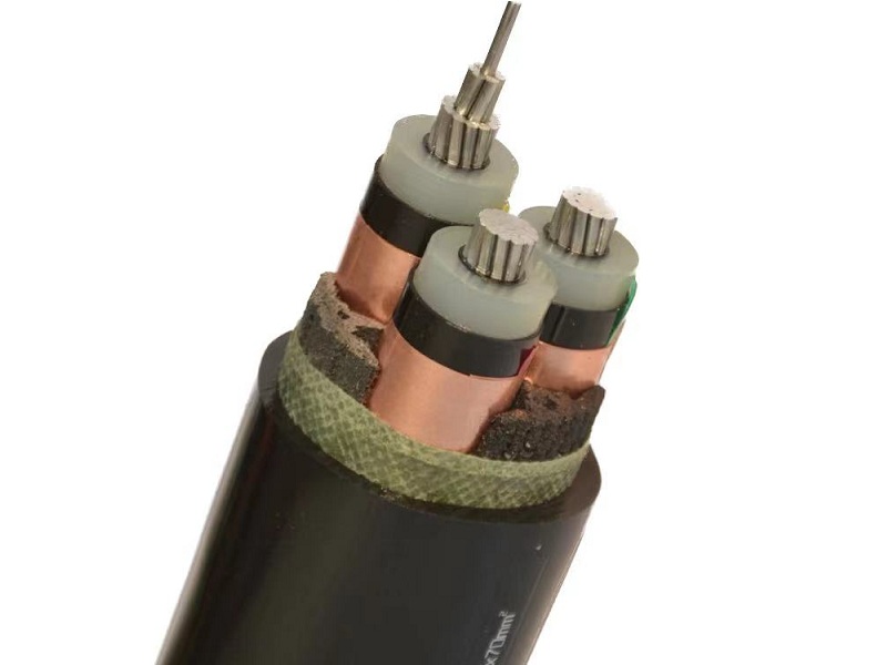
Three Core 21/35KV (Um=42KV) Unarmored Cable
Voltage: 21/35kV
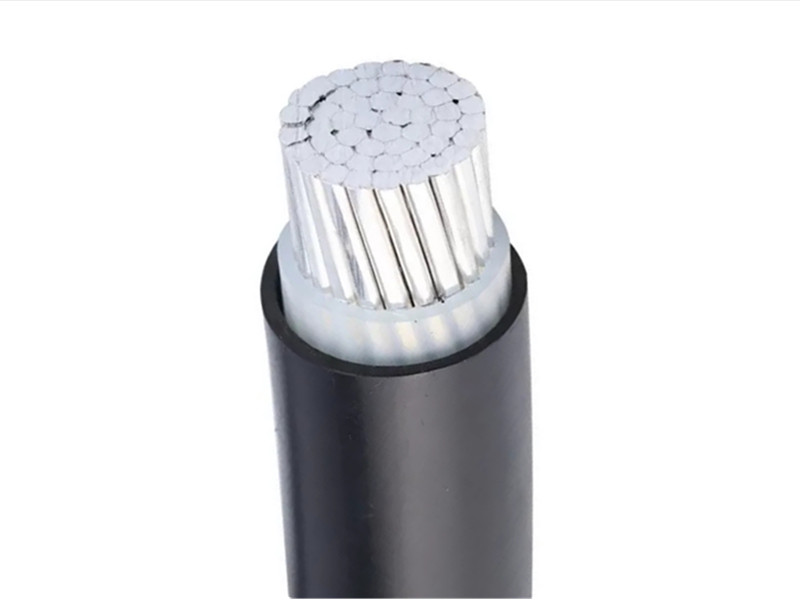
Conductor: Copper or Aluminum
Operating Temperature: up to 90°C
Short Circuit Temperature: 250°C
Bending Radius: 15 x OD
Email: manager@hdcable.com.cn
XLPE(Cross linked polyethylene) insulated cable functions well for electricity transmission and distribution lines for its excellent electrical and physical properties, including the advantage of simplicity in construction, lightness in weight; convenience in application besides its excellent electrical, thermal, mechanical and anti-chemical corrosion properties.
GB/12706-2008, IEC60502,IEC 60228,IEC60332 BS 5467,BS 6622 , IS 1554 , IS 7098and ICEA S-66-524 etc.
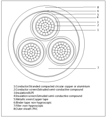
Conductor: Plain annealed stranded compacted circular copper or aluminium conductor to IEC60228 class 2
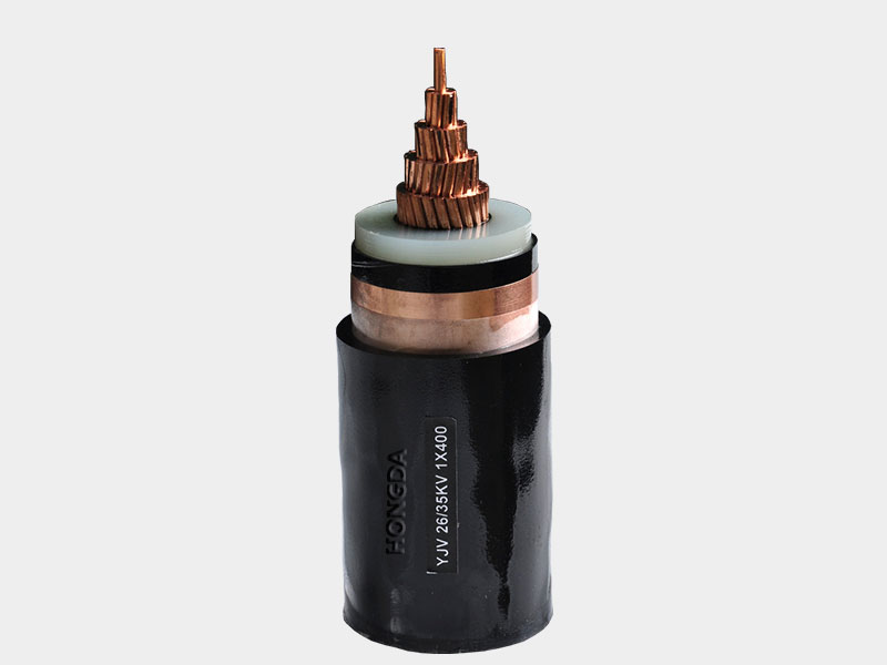
Conductor Screen: Extruded semi-conductive compound
Insulation: XLPE (cross-linked polyethylene) rated at 90°C
Insulation Screen: Extruded semi-conductive compound
Metallic Screen: copper tape or a concentric layer of copper wires
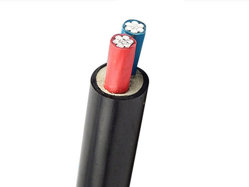
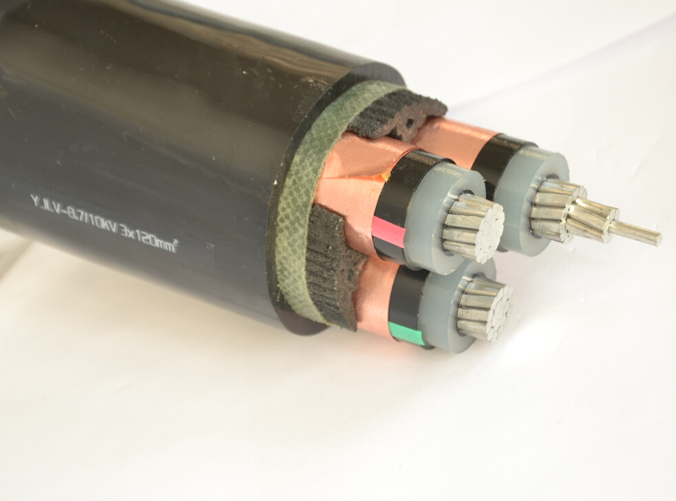
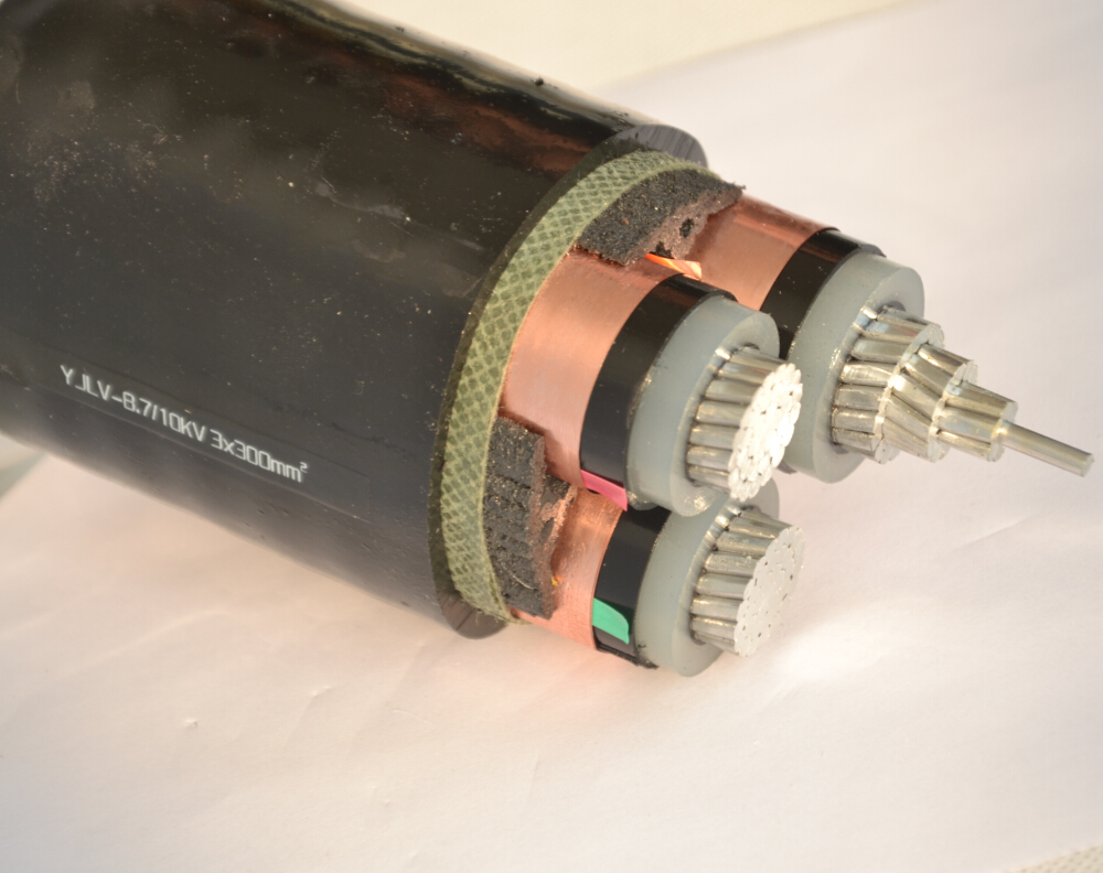
Color for core identification: Red, Yellow ,Blue tape shall be applied between insulation screen and metallic screen ( The above identifying can be changed as user requirement)
Assembly : Three screened cores are laid up together ,if necessary filled with non-hygroscopic material compatible with insulation and covered with a layer of PVC sheath
Outer Sheath: PVC type ST2 to IEC 60502 or PE ,LSZH
|
Specification |
Outer diameter |
Nominal thickness of insulation |
Nominal sheath thickness |
Approx.outer diameter of cable |
Approx. Weight of cable |
Ampacity of cable |
||||
|
Air |
Soil |
|||||||||
|
CU |
AL |
Cu |
Al |
Cu |
Al |
|||||
|
mm2 |
mm |
mm |
mm |
mm |
kg/km |
kg/km |
A |
A |
A |
A |
|
3×50 |
8.4 |
9.3 |
3.3 |
73.0 |
5340.0 |
4407.4 |
180 |
140 |
190 |
145 |
|
3×70 |
10.0 |
9.3 |
3.4 |
76.7 |
6199.7 |
4894.0 |
220 |
170 |
230 |
180 |
|
3×95 |
11.5 |
9.3 |
3.6 |
80.1 |
7209.1 |
5437.0 |
265 |
205 |
275 |
215 |
|
3×120 |
13.0 |
9.3 |
3.7 |
83.6 |
8219.5 |
5981.0 |
305 |
235 |
315 |
245 |
|
3×150 |
14.5 |
9.3 |
3.8 |
87.0 |
9370.1 |
6572.0 |
345 |
270 |
355 |
275 |
|
3×185 |
16.2 |
9.3 |
3.9 |
90.9 |
10693.5 |
7242.5 |
390 |
305 |
400 |
310 |
|
3×240 |
18.4 |
9.3 |
4.1 |
96.0 |
12660.0 |
8183.1 |
455 |
355 |
460 |
360 |
|
3×300 |
20.5 |
9.3 |
4.2 |
100.8 |
14749.0 |
9152.8 |
525 |
410 |
520 |
410 |
|
3×400 |
23.5 |
9.3 |
4.4 |
107.8 |
18099.7 |
10638.4 |
600 |
470 |
590 |
465 |
|
Nominal section area (mm2) |
Copper conductor(Ω/km) |
Aluminum conductor(Ω/km) |
|
1.5 |
12.1 |
- |
|
2.5 |
7.41 |
12.1 |
|
4 |
4.61 |
7.41 |
|
6 |
3.08 |
4.61 |
|
10 |
1.83 |
3.08 |
|
16 |
1.15 |
1.91 |
|
25 |
0.727 |
1.20 |
|
35 |
0.524 |
0.868 |
|
50 |
0.387 |
0.641 |
|
70 |
0.268 |
0.443 |
|
95 |
0.193 |
0.320 |
|
120 |
0.153 |
0.253 |
|
150 |
0.124 |
0.206 |
|
185 |
0.0991 |
0.164 |
|
240 |
0.0754 |
0.125 |
|
300 |
0.0601 |
0.100 |
|
400 |
0.0470 |
0.0778 |
|
500 |
0.0366 |
0.0605 |
|
630 |
0.0283 |
0.0469 |
Max. Permissible short-circuit current for conductor (reference value)
|
Nominal section area (mm2) |
Maximum permissible short-circuit current for conductor(1s)(KA) |
|
|
Copper conductor |
Aluminum conductor |
|
|
1.5 |
0.12 |
0.13 |
|
2.5 |
0.32 |
0.22 |
|
4 |
0.50 |
0.34 |
|
6 |
0.76 |
0.51 |
|
10 |
1.51 |
0.99 |
|
16 |
2.39 |
1.56 |
|
25 |
3.69 |
2.42 |
|
35 |
5.15 |
3.37 |
|
50 |
7.31 |
4.79 |
|
70 |
10.2 |
6.68 |
|
95 |
13.8 |
9.03 |
|
120 |
17.4 |
11.4 |
|
150 |
21.7 |
14.2 |
|
185 |
26.7 |
17.5 |
|
240 |
34.6 |
22.6 |
|
300 |
43.1 |
28.2 |
|
400 |
57.4 |
37.65 |
|
500 |
71.7 |
47.0 |
|
630 |
88.8 |
58.0 |